Electrical Series Circuits
Voltage and current in electrical series circuits.
A series circuit has only one path for the electrons to flow.
The Series Circuit Rules:
- The total current in the circuit is equal to the current in any other part of the circuit.
- The total voltage in a series circuit is equal to the sum of the voltages across all parts in the circuit.
- The total resistance in a series circuit is equal to the resistances of all parts in the circuit.
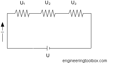
In series circuits the sum of voltages is equal to the applied voltage and can be expressed as
U = U1 + U2 + ... + Un (1)
where
U = applied voltage from the battery or source (volts, V)
U1..n = voltage over each resistor (volts, V)
From Ohms Law
Un = In Rn (2)
where
In = current (amps, A)
Rn = resistance (ohms, Ω)
According rule 1 the currents in a series circuit are equal. This can be expressed as
I1 = I2 = .. = In (3)
- equation (1) can be modified to
R = R1 + R2 + .. + Rn (4)
where
R = total circuit resistance in the circuit (ohms, Ω)
Example - Series Circuit
Three resistors - 1.25 Ω, 0.5 Ω and 1.5 Ω - are connected in series to a 12 V car battery. The total resistance in the circuit can be calculated as
R = (1.0 Ω) + (0.5 Ω) + (1.5 Ω)
= 3 Ω
The current in the series circuit can be calculated as
I = U / R
= 12 / 3
= 4 amps
The power dissipated in the circuit can be calculated
P = R I2
= (3 Ω) (4 amps)2
= 48 watts


